Making a desulfator modifying an AC adapter for a laptop
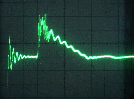
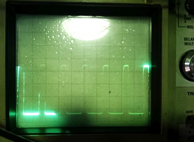
This desulfator makes pulses shown below and this sure can revive
sulfated batteries.
 p { margin-bottom: 0.25cm; line-height: 120%; }a:link { }
 X: 5μsec/div. Cycle is about 50μsec with some jitter
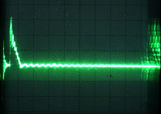
 Run in part. negative peak -4.5A. X: 100nsec/div
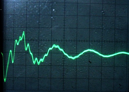
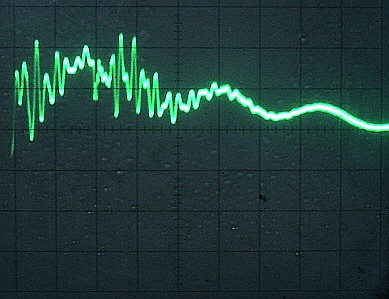 Current peak 6.6A X: 200nsec/div
 Modified AC adapter for a laptop
I happened have informed about a desulfator which de-sulfate
a car battery by a friend of mine. His purpose was to use aged
batteries that weren't good enough to use for automobiles any
more due to the increased internal ESR caused by the sulfation.
He has a home made solar system designed to work at 24V and
he uses 2 car batteries in series. His desulfator is almost the
same with this one explained here below.
http://fucimin.altervista.org/desulf/desulfator.pdf
The power source of above is the battery itself and a battery
charger is needed separately when to use because the battery
is discharged while desulfating and becomes empty as the
desulfation goes on.
I happened to find a patent below when searching the Net
and it explains about the actual frequencies and the current.
Patent: Pulse generation device for charging a valve-
regulated lead-acid battery
https://patents.google.com/patent/WO2004070909A1/en
The important figures are claimed as below.
4. A pulse generation device as claimed in claim 2,
wherein said first frequency is in the range of 50 kHz
to150 kHz and said second frequency is in the range
of 10 Hz to 500 Hz.
5. A pulse generation device as claimed in claim 1,
wherein said pulses are square wave pulses.
6. A pulse generation device as claimed in claim 2,
wherein the first frequency pulses have an on time
in the range of 1 to 10 μs and an average current
in the range of 20mA to 60 mA.
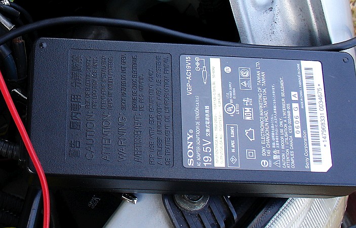
When I was reading the contents, I got an idea to make a unique
desulfator which can charge and desulfate the battery at the
same time. My idea is to modify an AC adapter for a laptop PC.
Many of those AC adapter has a out put of DC 19-20V range
with a PFC circuit to meet the regulation of the power factor.
Most of those stop the PFC function when the load is small
and the deactivation is useful to get the second frequency
explained at the number 4.
Below is the result of 4 days after the desulfation was started.
I also took a photo just when started but I can't find it now.
I remember almost all the part was white then.
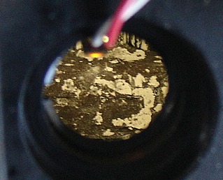 Day 4.
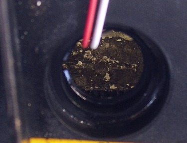 Day 14.
You can see how the sulfation was decreased. Actually the
battery became quite OK to start the engine easily.
Before the desulfation was done, no matter how I charges the
battery using a regular charger,it was impossible to start the
engine.
sulfated batteries.
Currentwaveform to a battery 40B. Y=2A/div, X=1us/div
I happened have informed about a desulfator which de-sulfate
a car battery by a friend of mine. His purpose was to use aged
batteries that weren't good enough to use for automobiles any
more due to the increased internal ESR caused by the sulfation.
He has a home made solar system designed to work at 24V and
he uses 2 car batteries in series. His desulfator is almost the
same with this one explained here below.
http://fucimin.altervista.org/desulf/desulfator.pdf
The power source of above is the battery itself and a battery
charger is needed separately when to use because the battery
is discharged while desulfating and becomes empty as the
desulfation goes on.
I happened to find a patent below when searching the Net
and it explains about the actual frequencies and the current.
Patent: Pulse generation device for charging a valve-
regulated lead-acid battery
https://patents.google.com/patent/WO2004070909A1/en
The important figures are claimed as below.
4. A pulse generation device as claimed in claim 2,
wherein said first frequency is in the range of 50 kHz
to150 kHz and said second frequency is in the range
of 10 Hz to 500 Hz.
5. A pulse generation device as claimed in claim 1,
wherein said pulses are square wave pulses.
6. A pulse generation device as claimed in claim 2,
wherein the first frequency pulses have an on time
in the range of 1 to 10 μs and an average current
in the range of 20mA to 60 mA.
When I was reading the contents, I got an idea to make a unique
desulfator which can charge and desulfate the battery at the
same time. My idea is to modify an AC adapter for a laptop PC.
Many of those AC adapter has a out put of DC 19-20V range
with a PFC circuit to meet the regulation of the power factor.
Most of those stop the PFC function when the load is small
and the deactivation is useful to get the second frequency
explained at the number 4.
Below is the result of 4 days after the desulfation was started.
I also took a photo just when started but I can't find it now.
I remember almost all the part was white then.
You can see how the sulfation was decreased. Actually the
battery became quite OK to start the engine easily.
Before the desulfation was done, no matter how I charges the
battery using a regular charger,it was impossible to start the
engine.
Mirage ECU problem
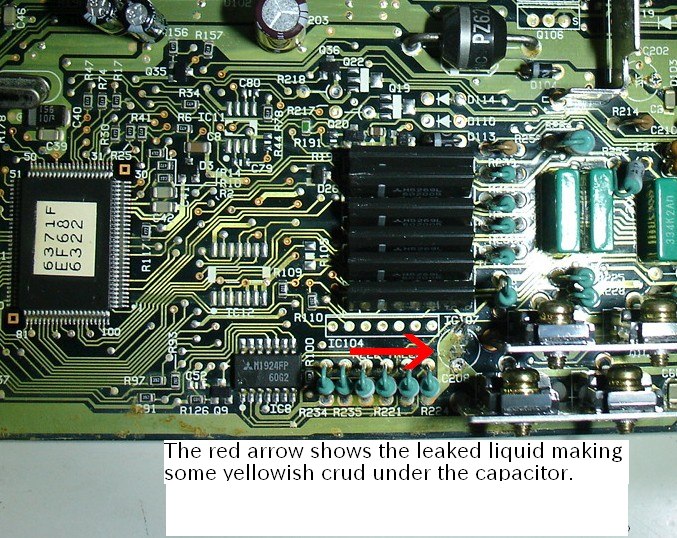
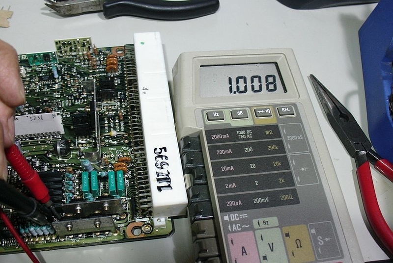
The photo below shows a part of failed ECU for a 96 Mirage 115000km.
It didn't communicate with a scanner.The car had an engine fluctuating
problem too.
A local dealership manager asked me for a help sending me a
message below.
"We are having a hard time fixing the car. The ECU and the scanner
didn't communicate at all and we couldn't read the error code.
The engine fluctuated and we've tried our best, replacing a
PCV valve, cleaning the throttle body and changing the PCV valve.
But the problem persists and now we have no idea to go further.”
I'm just a DIYer and I can't make a big deal, but for some reason,
I understand some of the electronics.
When I examined the board,the ripple voltage at the Vcc lines, there
were spikes and ripples and it was natural that it couldn't communicate
with the scanner connected.
Looking at the mounted board,Nichicon's electrolytic capacitors
P series were used. Although no leak could be visually confirmed,
when ESR was examined, one was completely dead and the other
showed high values. I removed the dead one and found the leaked
liquid was solidified on the board as shown in the first picture, and it
showed about 1kΩ/1mm distance by an ohm meter as below.
The car now runs fine, but the problem of fluctuating idling has not
been solved. I had already done an experiment to find out the
cause of it using a home made smoke machine. It was caused by
a worn O ring used at the throttle shaft. The air was absorbed there.
It didn't communicate with a scanner.The car had an engine fluctuating
problem too.
message below.
"We are having a hard time fixing the car. The ECU and the scanner
didn't communicate at all and we couldn't read the error code.
The engine fluctuated and we've tried our best, replacing a
PCV valve, cleaning the throttle body and changing the PCV valve.
But the problem persists and now we have no idea to go further.”
I'm just a DIYer and I can't make a big deal, but for some reason,
I understand some of the electronics.
When I examined the board,the ripple voltage at the Vcc lines, there
were spikes and ripples and it was natural that it couldn't communicate
with the scanner connected.
Looking at the mounted board,Nichicon's electrolytic capacitors
P series were used. Although no leak could be visually confirmed,
when ESR was examined, one was completely dead and the other
showed high values. I removed the dead one and found the leaked
liquid was solidified on the board as shown in the first picture, and it
showed about 1kΩ/1mm distance by an ohm meter as below.
been solved. I had already done an experiment to find out the
cause of it using a home made smoke machine. It was caused by
a worn O ring used at the throttle shaft. The air was absorbed there.
Security alarm malfunctions on a Daihatsu Mila. The root cause of it. L275S ダイハツ・ミラ セキュリティー誤動作とその原因
L275S ミラの盗難警報が誤動作してお困りの方が多く、近くのショップ
でも、それでお困りでした。店主様からSOSをもらい、その根本原因を
調べたので、日本語でサマリーを先に書いておきます。アメリカの友達たち
向けに私が書いているブログは、英語で書く必用があり、そうしていますが、
ミラは国内専用車種なので、日本語で書かないといけないと指摘されて
しまいました。
問題の根源は、リアゲートの検出スイッチ周りに水分が入り込むと、
電流リークが起きることでした。
の間でリークが起きるからですが、異種金属の組み合わせによる
ガルバニック反応で電池ができ、800mVもの電圧が発生することが、誤動作
を助長します。スイッチに付けられたクッション性のゴムは水分を吸着し易く
これが2つの異種金属の間で電解質として働き、電池を形成するということ
までをダイハツのエンジニアは考えられなかったのが、市場不良多発に
つながったとも言えます。
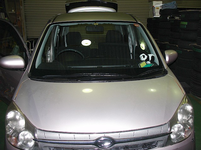
The owner of the car below was upset due to the fact that the problem
was happened at a middle of night. It happened all of the sudden when
no one was there.
The problem was the malfunction of the security system and it
was not duplicated after that for months. But it happened again just
once recently and it was impossible to duplicate the malfunction.
I was requested to help by a local car shop owner to solve the problem.
He has been trying to duplicate the problem and find the reason why
the malfunction was caused. He has needed to fix it finding the root
cause of it since the complain from his customer was very serious.
But his efforts so far have been not successful. Whatever he tried,
the result was just a vain. The occurrence was very seldom and could
not be duplicated. Then he decided to call me.
As he and I checked the Internet, there were so many posts about
the problem but we couldn't find any definitive answers or solutions.
You can see how there are so many malfunction problems in the fields.
Some owners were quite angry with the problem. Judging from the
announcement by the manufacturer listed at the bottom with *,
they too are struggling. Every post below is in Japanese since the
car is only sold in Japan. Use the Google Translation if you need to
understand the contents.
ダイハツミラ盗難警報装置誤作動とディーラー対応
http://spiritualworld.cocolog-nifty.com/blog/2013/01/2013110-ff10.html
車の防犯ブザーが鳴るのを解除したいのですが、....
http://gizport.jp/gp/question/1792270/?id=20045823
L275S ミラのセキュリティアラーム
https://oshiete.goo.ne.jp/qa/9781751.html
L275Sミラカスタムのセキュリティー誤作動。
https://minkara.carview.co.jp/userid/1033221/blog/41039837/
純正セキュリティー 誤作動 L275S ミラ
https://blogs.yahoo.co.jp/nikocyanndai/56325201.html
ダイハツのミラですが、先程いきなりセキュリティアラ...
https://detail.chiebukuro.yahoo.co.jp/qa/question_detail/q1158084331
大至急!ダイハツのミラに乗っています。数日前から...
https://detail.chiebukuro.yahoo.co.jp/qa/question_detail/q11185197756
家の中にいたら、駐車場に置いてある車のカーアラー...
https://detail.chiebukuro.yahoo.co.jp/qa/question_detail/q10177687820
* キーフリーシステム装着車をご使用のお客様へ
https://www.daihatsu.co.jp/service/carlife/carlife_1.htm
As I read above and hear from the shop owner, the malfunction tends to
happens when it's badly raining of after that. The rain water may be related
and doing something, I imagined.
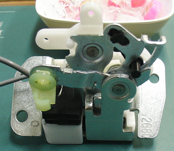
There are 5 switches for the detection. Each door/gate has it's own switch.
There are 5 switches for the detection. Each door/gate has it's own switch.
One or more of them may be malfunctioning or the loom to those may be
leaking or the MPX body computer may be malfunctioning.
As I checked the internal circuits of the MPX body computer where the
As I checked the internal circuits of the MPX body computer where the
security circuit was built in, I found that the sensing line B5 is pulled up
to 5.0V DC line via a diode with a 680 ohms series resistor. This pin is
the input pin for 5 switches. All those 5 are paralleled and connected
to here. I must say the line is rather high impedanced. High here means
that the current draw at the line is sensitive. A slight leakage may cause
the problem. Actually pouring small amount of water to the rear gate
switch causes the malfunction and the problem is duplicated easily.
The switch is covered with a cushion rubber as is shown in the photos
below. It absorbs the water and the insulation between the switch
contact plate and the body became poor. In addition to that, the
material used for the contact is the beryllium copper and this makes
a battery with the base material zinc plated steel when the cushion
rubber is wet. As I check the voltage, it shows around 800mV.
Come to think of it, the beryllium copper's galvanic voltage is around
-0.2V and the zinc plated steel's -1.0V. It is natural these 2 metals
make the voltage difference of 800mV. The voltage affects the
sensitivity too. You can find galvanic voltages here.
http://l-36.com/corrosion.php
http://l-36.com/corrosion.php
After the black cushion rubber is removed.
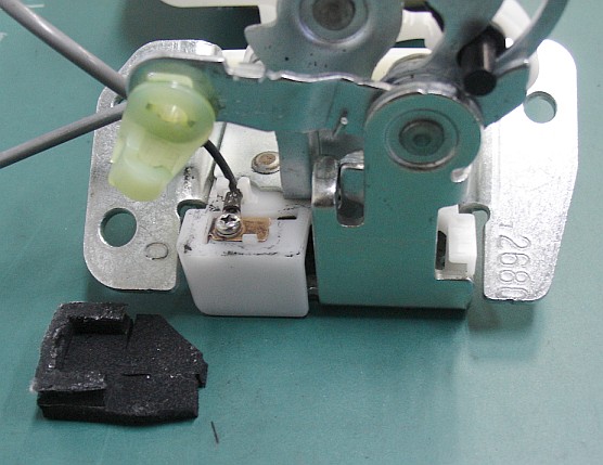
The black one absorbs water very well and this makes a current bridge
between the contact and the zinc plated steel frame.
I don't say this is a design fault but it is not a good idea to use a
cushion rubber just above the switch for the rear gate.
The designer's intention must be to protect the switch contacts
against dusts and other foreign objects falling from above but
he should have to think about the side effects such as a moisture.
It sure causes the current leaking problem between the contact
and the body easily when the rubber is wet. In addition to that,
there makes a 800mV battery due to the Galvanic series and
this accelerates the problem. I was easily duplicated problem
just poring water there. If I were him, I wouldn't design that way.
I'd use a moisture free switch such as a lead switch there to
prevent the malfunction of the security system especially when
rained or the humidity is high enough to have water condensations.
p { margin-bottom: 0.25cm; line-height: 120%; }a:link { }
Fixing an old tachometer
My local car shop owner asked me for a help. He was having a
problem with a non working tachometer used for a 93 Celica GT.
He has tried to replace the tachometer but it was totally
impossible to obtain any new or used one.
The car is 25 years old and the parts availability is now quite
low. But the car itself looks very new both inside and out.
The car was designed and made at the golden era of Toyota.
The engine runs well too and he really wanted to fix the
tachometer expecting me to do it.
He quickly removed the cluster unit from the dashboard and
showed it to me although he was busy doing another project
when I visited.
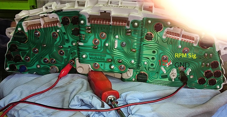
Below is the rear view of it. The tachometer is held by 3
screws as is shown. Those 3 are also used for the terminals
to supply +12V, to connect to the ground and the RPM in signal
judging from traces and other components surrounded.
So removing those 3 screws makes it possible to remove
the tachometer unit from the cluster and check it at a bench.
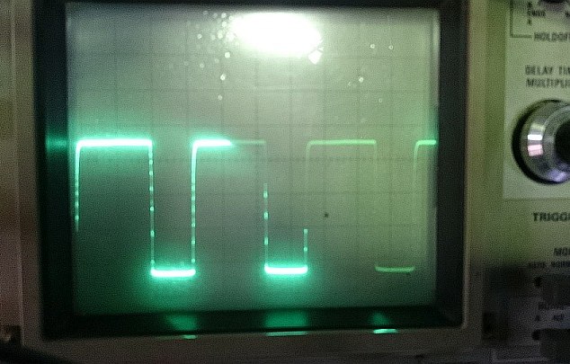
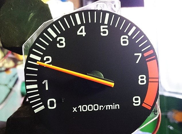
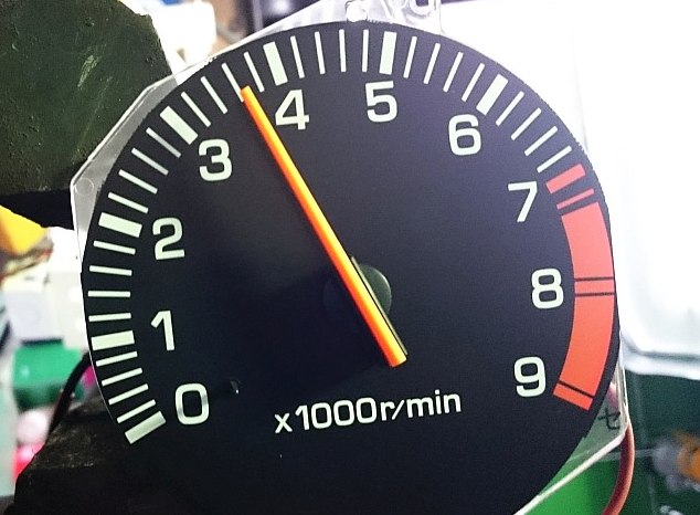
the 60Hz or 120Hz signals from a simple home made signal
generator. The reason why it is simple is that the signal
source is not generated inside but is getting the 60Hz energy
from the power company. It is consisting of a modified AC
adapter and a circuit to make square waves of 60Hz and
120Hz. A 60Hz square wave signal can drive the tachometer
to indicate 1800rpm and 120Hz, 3600rpm in case of a 4 cylinder
engine. Probably you may wonder why a power company's
60Hz can be used for the check of a tachometer. I will be
explaining it later.
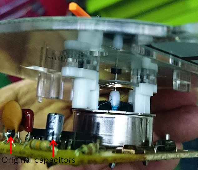
As I checked the board behind the tachometer panel, there
were 2 electrolytic capacitors 10uF/25V. Those 2 had a
symbol mark of Matsushita. These days I have been
experiencing problems caused by aged Matsushita's
electrolytic capacitors. They were commonly dried up
badly. Of course electrolytic capacitors will dry up some
day in accordance with the Arrhenius equation, but
Matsushita's ones dry up quicker than other major
Japanese brands due to the reason that the rubber
becomes more brittle than others according to my
experience. Actually, I recently had a door's lock/unlock
problem on a 18 years old Subaru Pleo and it was caused
by old Matsushita's electrolytic capacitors. With these
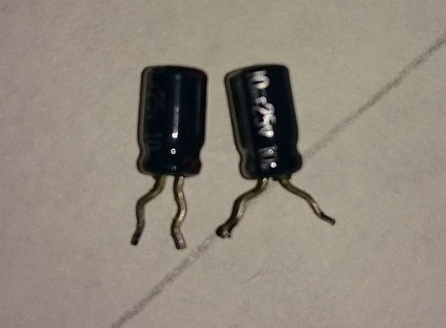
my own experience, I dare removed those 2 capacitors
and replaced with new ones manufactured by Nippon
Chemion. Speaking of electrolytic capacitors, QAS capacitors
fabricated by Nichicon also end the life quicker than others
and auto mobile industries had some impact. One example is
the Celsior / LS400's ECU witten here below by a friend of mine.
https://www.clublexus.com/forums/ls-1st-and-2nd-gen-1990-2000/656360-all-my-crazy-lexus-issues-solved-ecu-leaking-capacitor.html
We have to be careful for aged electrolytic capacitors especially
the one with the QAS liquid inside and some company's one with
a rubber which becomes very hard like a plastic and brittle as
are like those 2 used for a Celica's tachometer.
one showed more than 600ohms and the other infinity.
These were surely dead or almost so.
applying 60Hz and 120Hz attaching the signal generator.
After installing the cluster unit to the dashboard, the shop
owner said, “It's working perfectly. Thanks for the help and
I'll take you to a dinner appreciating your efforts”.
I am counting on what he'll serve me.
p { margin-bottom: 0.25cm; line-height: 120%; }p { margin-bottom: 0.25cm; line-height: 120%; }
problem with a non working tachometer used for a 93 Celica GT.
He has tried to replace the tachometer but it was totally
impossible to obtain any new or used one.
The car is 25 years old and the parts availability is now quite
low. But the car itself looks very new both inside and out.
The car was designed and made at the golden era of Toyota.
The engine runs well too and he really wanted to fix the
tachometer expecting me to do it.
He quickly removed the cluster unit from the dashboard and
showed it to me although he was busy doing another project
when I visited.
Below is the rear view of it. The tachometer is held by 3
screws as is shown. Those 3 are also used for the terminals
to supply +12V, to connect to the ground and the RPM in signal
judging from traces and other components surrounded.
So removing those 3 screws makes it possible to remove
the tachometer unit from the cluster and check it at a bench.
the 60Hz or 120Hz signals from a simple home made signal
generator. The reason why it is simple is that the signal
source is not generated inside but is getting the 60Hz energy
from the power company. It is consisting of a modified AC
adapter and a circuit to make square waves of 60Hz and
120Hz. A 60Hz square wave signal can drive the tachometer
to indicate 1800rpm and 120Hz, 3600rpm in case of a 4 cylinder
engine. Probably you may wonder why a power company's
60Hz can be used for the check of a tachometer. I will be
explaining it later.
As I checked the board behind the tachometer panel, there
were 2 electrolytic capacitors 10uF/25V. Those 2 had a
symbol mark of Matsushita. These days I have been
experiencing problems caused by aged Matsushita's
electrolytic capacitors. They were commonly dried up
badly. Of course electrolytic capacitors will dry up some
day in accordance with the Arrhenius equation, but
Matsushita's ones dry up quicker than other major
Japanese brands due to the reason that the rubber
becomes more brittle than others according to my
experience. Actually, I recently had a door's lock/unlock
problem on a 18 years old Subaru Pleo and it was caused
by old Matsushita's electrolytic capacitors. With these
my own experience, I dare removed those 2 capacitors
and replaced with new ones manufactured by Nippon
Chemion. Speaking of electrolytic capacitors, QAS capacitors
fabricated by Nichicon also end the life quicker than others
and auto mobile industries had some impact. One example is
the Celsior / LS400's ECU witten here below by a friend of mine.
https://www.clublexus.com/forums/ls-1st-and-2nd-gen-1990-2000/656360-all-my-crazy-lexus-issues-solved-ecu-leaking-capacitor.html
We have to be careful for aged electrolytic capacitors especially
the one with the QAS liquid inside and some company's one with
a rubber which becomes very hard like a plastic and brittle as
are like those 2 used for a Celica's tachometer.
one showed more than 600ohms and the other infinity.
These were surely dead or almost so.
applying 60Hz and 120Hz attaching the signal generator.
After installing the cluster unit to the dashboard, the shop
owner said, “It's working perfectly. Thanks for the help and
I'll take you to a dinner appreciating your efforts”.
I am counting on what he'll serve me.
Regarding the home made signal generator, originally
it was a AC adapter of a 6VDC. I added 2 rectifying
diodes inside to get the half-wave rectified waveform
and the full-wave rectified waveform. Using a Schmitt
it was a AC adapter of a 6VDC. I added 2 rectifying
diodes inside to get the half-wave rectified waveform
and the full-wave rectified waveform. Using a Schmitt
trigger circuit, those are converted to square waves of
60Hzand 120Hz. A 4cycles of 4 cylinders engine's
60Hzand 120Hz. A 4cycles of 4 cylinders engine's
revolution 1800rpm means 30rps and the engine ignites
2 times at each revolution. This means that there are
60 ignitions in 1 second. This is the reason why a power
company's 60Hz energy can drive the tachometer
1800rpm and the twice frequency 120Hz, 3600rpm.
This simple method is enough for us to check the
tachometer without buying an expensive signal
generator. This certainly is a poor man's method
but quite effective to check a tachometer as well
as a speedometer since 60Hz drives the speedometer
85km/H and 120Hz, 170km/H.
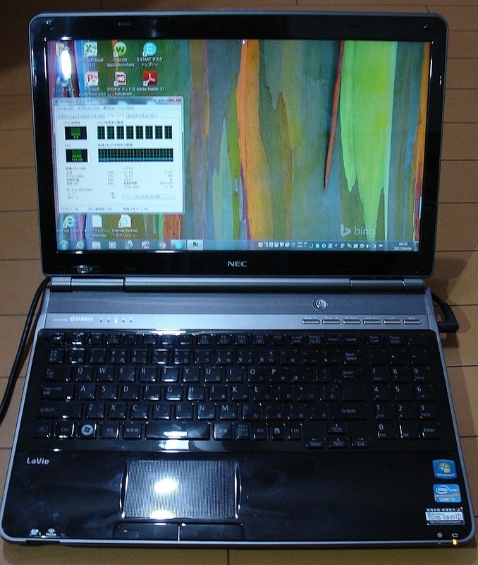
Another NEC PC killed by a ceramic capacitor
This time, I was requested to fix a NEC PC-LL750F26B. It has a
CPU Core i7-2670QM and the memory 8GB. It's not very new
but it's too early to discard. As you see the photo below, it says
Core i7.
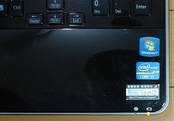 The label says, "CORE i7".
I have once experienced a short circuited problem of a ceramic
capacitor used for a NEC laptop at here.
https://blogs.yahoo.co.jp/mae_yas/11468574.html
As I have written above, there were many similar problems among
NEC PCs in the market. When one of ceramic capacitors used
for the bypass purpose is short circuited internally, it is not easy
to find out which one is failed since there are many other ceramic
capacitors in parallel with it.
The last time when I fixed the lap top NEC PC-LS150BS6W, I only
needed to use a multimeter which can read down to 0.01Ω to
find out the exact short circuited one since it showed the
resistance 0.01Ω smaller than others and rather easy to distinguish.
This time the symptom was completely no power. Nothing has
happened when the power button was pushed on. No LED nor no
screen lit as if the AC adapter / battery was dead. As I checked
the inside using a multimeter, I found the DC line for the primary
side of the CPU power block and others showed only 0.3 Ω or so.
The photo below shows the resistance at the power supply line.
It is close to the connector where the external AC adapter is
connected. It showed 0.30Ω to 0.33 Ω depending on the
pressure to apply to the capacitor's terminals. When the
photo below was taken, I had to hold the camera by my right
hand and my left hand was barely holing the 2 test leads.
I was not able to give terminals enough pressure and the
read out showed 0.33Ω.
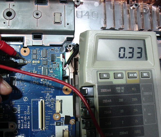 Showed 0.33Ω when leads barely touched
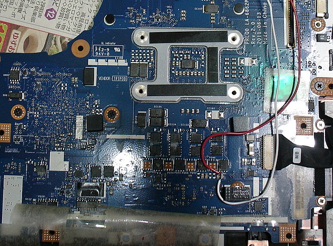
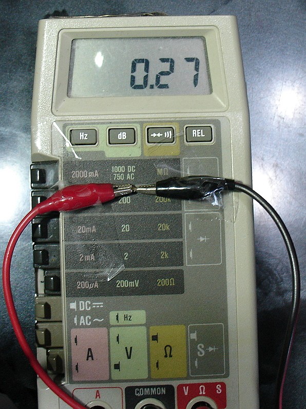
The lowest resistance 0.27Ω was found at the primary side of
CPU's power circuit. There are 4 ceramic capacitors very close
to each other and all of them showed 0.27Ω. The photo below
shows the location where the lowest resistance was confirmed
and I connected wires to supply the current using a low voltage
DC power supply unit. As you see below there are 4 capacitors near
the red and white leads are soldered. All these are in parallel.
Connecting a low voltage power supply unit, I used an infra-red
thermometer which area was warmer than others.
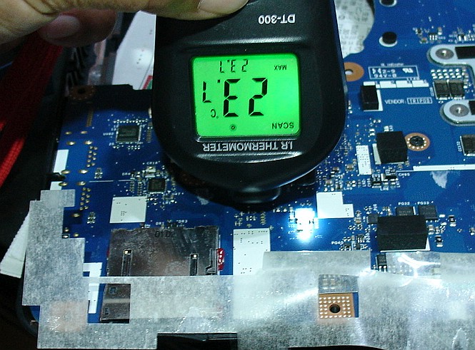
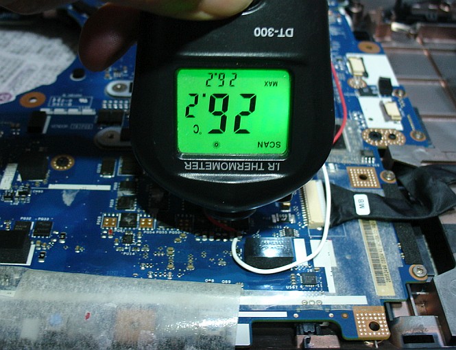
I found that the primary side of the CPU power supply was warmer
than others and this explained why the resistance was lowest there.
I also determined which one out of 4 is failed. The voltage is 0.332V
and this does not go through semiconductors but can go through
resistors. So we can find the semi short-circuited capacitor easily.
There still existed 0.27Ω and this should heat up the capacitor.
Suppose the current is 1A, theoretically the power consumed
by the capacitor is given as follows.
P=I X I X 0.27
For an example, when I is 1A,
P=1A X 1A X 0.27Ω
=0.27W.
The actual low voltage DC power unit is as below.
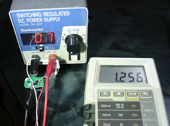
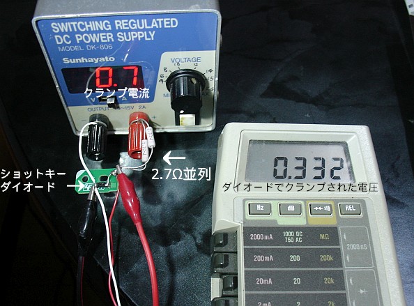
The voltage of the unit is 1.256V when the nob is set minimum
and is still high for semiconductors. So I added 2 resistors in
parallel and a schottkey diode to limit the current and the
voltage. The resistor I used was 1.35Ω(2 X 2.7Ω parallel) and
this limits the current up to 0.93A (1.256V/1.35Ω=0.93A).
The schottkey diode is EC31QS03L(Io 3A, Vrrm 30V, Vf 0.45V max)
to limit the voltage. In my application, the actual clamped
voltage is around 0.33V or so as you can see in the photo above.
When the output is open, the voltage is limited up to 0.33V and
the maximum current is limited 0.948A theoretically by resistors.
The capacitor had remaining resistance of 0.27Ω and the
maximum current should be limited 1.256V/1.35Ω + 0.27Ω ≒ 0.78A.
Applying the current, I touched the second capacitor from the
right side by my index finger, I felt some extra heat and confirmed
it was the culprit. Replacing it fixed the problem. The removed
capacitor showed the resistance 0.27Ω. I had no idea to know
the original capacitance but judging from the application,
I dare used a 1uF ceramic capacitor manufactured by a Japanese
company Murata which I trust a lot.
Now the PC powers up and works well as it used to be.
I think I need to explain the low voltage power unit a bit more.
In addition to the DC power supply, I used external resistors
1.35Ω(2 X 2.7Ω parallel) to limit the current. The schottkey
diode was EC31QS03L(Io 3A, Vrrm 30V, Max Vf 0.45V) aiming
to limit the voltage. Adding these parts allowed me to supply
the DC to the main board without damaging semiconductors.
This is based on the theory "Fermi level".
CPU Core i7-2670QM and the memory 8GB. It's not very new
but it's too early to discard. As you see the photo below, it says
Core i7.
I have once experienced a short circuited problem of a ceramic
capacitor used for a NEC laptop at here.
https://blogs.yahoo.co.jp/mae_yas/11468574.html
As I have written above, there were many similar problems among
NEC PCs in the market. When one of ceramic capacitors used
for the bypass purpose is short circuited internally, it is not easy
to find out which one is failed since there are many other ceramic
capacitors in parallel with it.
The last time when I fixed the lap top NEC PC-LS150BS6W, I only
needed to use a multimeter which can read down to 0.01Ω to
find out the exact short circuited one since it showed the
resistance 0.01Ω smaller than others and rather easy to distinguish.
This time the symptom was completely no power. Nothing has
happened when the power button was pushed on. No LED nor no
screen lit as if the AC adapter / battery was dead. As I checked
the inside using a multimeter, I found the DC line for the primary
side of the CPU power block and others showed only 0.3 Ω or so.
The photo below shows the resistance at the power supply line.
It is close to the connector where the external AC adapter is
connected. It showed 0.30Ω to 0.33 Ω depending on the
pressure to apply to the capacitor's terminals. When the
photo below was taken, I had to hold the camera by my right
hand and my left hand was barely holing the 2 test leads.
I was not able to give terminals enough pressure and the
read out showed 0.33Ω.
The lowest resistance 0.27Ω was found at the primary side of
CPU's power circuit. There are 4 ceramic capacitors very close
to each other and all of them showed 0.27Ω. The photo below
shows the location where the lowest resistance was confirmed
and I connected wires to supply the current using a low voltage
DC power supply unit. As you see below there are 4 capacitors near
the red and white leads are soldered. All these are in parallel.
Connecting a low voltage power supply unit, I used an infra-red
thermometer which area was warmer than others.
I found that the primary side of the CPU power supply was warmer
than others and this explained why the resistance was lowest there.
I also determined which one out of 4 is failed. The voltage is 0.332V
and this does not go through semiconductors but can go through
resistors. So we can find the semi short-circuited capacitor easily.
There still existed 0.27Ω and this should heat up the capacitor.
Suppose the current is 1A, theoretically the power consumed
by the capacitor is given as follows.
P=I X I X 0.27
For an example, when I is 1A,
P=1A X 1A X 0.27Ω
=0.27W.
The actual low voltage DC power unit is as below.
The voltage of the unit is 1.256V when the nob is set minimum
and is still high for semiconductors. So I added 2 resistors in
parallel and a schottkey diode to limit the current and the
voltage. The resistor I used was 1.35Ω(2 X 2.7Ω parallel) and
this limits the current up to 0.93A (1.256V/1.35Ω=0.93A).
The schottkey diode is EC31QS03L(Io 3A, Vrrm 30V, Vf 0.45V max)
to limit the voltage. In my application, the actual clamped
voltage is around 0.33V or so as you can see in the photo above.
When the output is open, the voltage is limited up to 0.33V and
the maximum current is limited 0.948A theoretically by resistors.
The capacitor had remaining resistance of 0.27Ω and the
maximum current should be limited 1.256V/1.35Ω + 0.27Ω ≒ 0.78A.
Applying the current, I touched the second capacitor from the
right side by my index finger, I felt some extra heat and confirmed
it was the culprit. Replacing it fixed the problem. The removed
capacitor showed the resistance 0.27Ω. I had no idea to know
the original capacitance but judging from the application,
I dare used a 1uF ceramic capacitor manufactured by a Japanese
company Murata which I trust a lot.
Now the PC powers up and works well as it used to be.
I think I need to explain the low voltage power unit a bit more.
In addition to the DC power supply, I used external resistors
1.35Ω(2 X 2.7Ω parallel) to limit the current. The schottkey
diode was EC31QS03L(Io 3A, Vrrm 30V, Max Vf 0.45V) aiming
to limit the voltage. Adding these parts allowed me to supply
the DC to the main board without damaging semiconductors.
This is based on the theory "Fermi level".
Fixing a clock spring
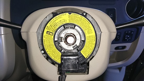
p { margin-bottom: 0.25cm; line-height: 120%; }
Seethe photo above. It's a clock spring used for a Mitsubishi
ek-Wagon. It intermittently turned on the air bag warning light.
A local car shop owner needed to fix it quickly and he asked
me for a help. He was in a hurry and also the customer didn't
want to spend any extra money to fix it except the labour charge.
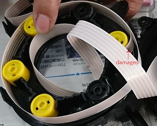
As I inspected the flexible cable inside, I found a damaged part
as was shown in the photo below.
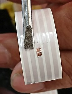
Peeling off the surface some, I soldered it and attached a polyimide
tape to insulate and to make it possible to slide easily. The tape
also adds some strength to the cable.
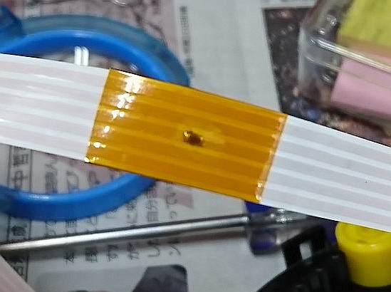
After installing the clock spring unit to the steering column, there's
no more warning light. It seems to be OK just soldering the damaged
part. I'm wondering how long it holds the connection. The car is already
rather old and I think it would be OK till the car is sent to a junk yard.
Fixing lights problem - Peugeot 307SW


help to fix troubled cars by local shop owners these days. Why?
Because they expect me to fix cars that can't be fixed by mechanics.
They are not good at modern cars that are equipped with many electronics
controlling circuits.
Today I worked together with a shop owner who was having a hard time to fix
a Peugeot 307SW which is shown at the top photo.
The problem was the headlights that turn on / off randomly without touching
anything. As I searched the Net, I found there were many similar problems among
Peugeot and Citroen cars in different countries. I also found that most of
them needed to replace the whole unit called com200X to fix as is written at below.
The stalk is not sold separately and the whole unit is needed change.
http://www.peugeotcentral.co.uk/ftopic-12887.html
The Citroen C3 also uses the same unit and there are similar problems too.
https://citroenc3owners.com/citroen-c3-tips/the-com2000-or-steering-wheel-stalks-an-inside-look-t467.html
The headlights are designed to turn on when the communication is failed
between the com200X and the BSI unit, I understand. This is to inform the
user that the communication error is occurred. The cause of the
failed communication is mostly caused by the unusual signal from the stalk.
The best way to fix is to replace the com2003X/BSI unit. But these
costs some big money. So what we did was to disassemble the stalk
to check conditions of contacts and those were like the last photo.
Those contacts were badly clogged. The dark part was completely oxidized
and there existed some big resistances. After I cleaned contacts, I used a
pencil 6B to wipe off the oxidized surface as well as to fill scratches
with the graphite and carbon to reduce the resistance. I also used a
contact restorer. After the job, the resistance became almost 0Ω.
After doing these, we installed the unit to the car and checked the
functions. We found that the problem was completely gone without replacing t
he unit. The shop owner said,"We did it".