Fixing an old tachometer
My local car shop owner asked me for a help. He was having a
problem with a non working tachometer used for a 93 Celica GT.
He has tried to replace the tachometer but it was totally
impossible to obtain any new or used one.
The car is 25 years old and the parts availability is now quite
low. But the car itself looks very new both inside and out.
The car was designed and made at the golden era of Toyota.
The engine runs well too and he really wanted to fix the
tachometer expecting me to do it.
He quickly removed the cluster unit from the dashboard and
showed it to me although he was busy doing another project
when I visited.
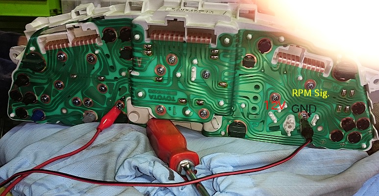
Below is the rear view of it. The tachometer is held by 3
screws as is shown. Those 3 are also used for the terminals
to supply +12V, to connect to the ground and the RPM in signal
judging from traces and other components surrounded.
So removing those 3 screws makes it possible to remove
the tachometer unit from the cluster and check it at a bench.
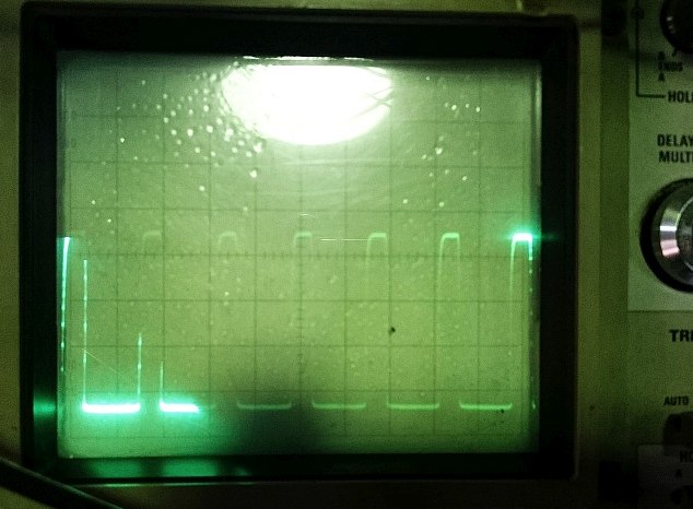
the 60Hz or 120Hz signals from a simple home made signal
generator. The reason why it is simple is that the signal
source is not generated inside but is getting the 60Hz energy
from the power company. It is consisting of a modified AC
adapter and a circuit to make square waves of 60Hz and
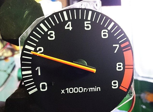
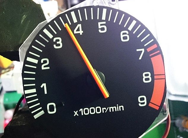
120Hz. A 60Hz square wave signal can drive the tachometer
to indicate 1800rpm and 120Hz, 3600rpm in case of a 4 cylinder
engine. Probably you may wonder why a power company's
60Hz can be used for the check of a tachometer. I will be
explaining it later.
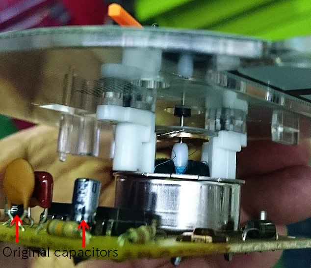
As I checked the board behind the tachometer panel, there
were 2 electrolytic capacitors 10uF/25V. Those 2 had a
symbol mark of Matsushita. These days I have been
experiencing problems caused by aged Matsushita's
electrolytic capacitors. They were commonly dried up
badly. Of course electrolytic capacitors will dry up some
day in accordance with the Arrhenius equation, but
Matsushita's ones dry up quicker than other major
Japanese brands due to the reason that the rubber
becomes more brittle than others according to my
experience. Actually, I recently had a door's lock/unlock
problem on a 18 years old Subaru Pleo and it was caused
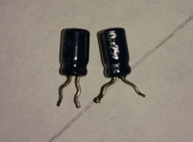
by old Matsushita's electrolytic capacitors. With these
my own experience, I dare removed those 2 capacitors
and replaced with new ones manufactured by Nippon
Chemion. Speaking of electrolytic capacitors, QAS capacitors
fabricated by Nichicon also end the life quicker than others
and auto mobile industries had some impact. One example is
the Celsior / LS400's ECU witten here below by a friend of mine.
https://www.clublexus.com/forums/ls-1st-and-2nd-gen-1990-2000/656360-all-my-crazy-lexus-issues-solved-ecu-leaking-capacitor.html
We have to be careful for aged electrolytic capacitors especially
the one with the QAS liquid inside and some company's one with
a rubber which becomes very hard like a plastic and brittle as
are like those 2 used for a Celica's tachometer.
one showed more than 600ohms and the other infinity.
These were surely dead or almost so.
applying 60Hz and 120Hz attaching the signal generator.
After installing the cluster unit to the dashboard, the shop
owner said, “It's working perfectly. Thanks for the help and
I'll take you to a dinner appreciating your efforts”.
I am counting on what he'll serve me.
p { margin-bottom: 0.25cm; line-height: 120%; }p { margin-bottom: 0.25cm; line-height: 120%; }
problem with a non working tachometer used for a 93 Celica GT.
He has tried to replace the tachometer but it was totally
impossible to obtain any new or used one.
The car is 25 years old and the parts availability is now quite
low. But the car itself looks very new both inside and out.
The car was designed and made at the golden era of Toyota.
The engine runs well too and he really wanted to fix the
tachometer expecting me to do it.
He quickly removed the cluster unit from the dashboard and
showed it to me although he was busy doing another project
when I visited.
Below is the rear view of it. The tachometer is held by 3
screws as is shown. Those 3 are also used for the terminals
to supply +12V, to connect to the ground and the RPM in signal
judging from traces and other components surrounded.
So removing those 3 screws makes it possible to remove
the tachometer unit from the cluster and check it at a bench.
the 60Hz or 120Hz signals from a simple home made signal
generator. The reason why it is simple is that the signal
source is not generated inside but is getting the 60Hz energy
from the power company. It is consisting of a modified AC
adapter and a circuit to make square waves of 60Hz and
120Hz. A 60Hz square wave signal can drive the tachometer
to indicate 1800rpm and 120Hz, 3600rpm in case of a 4 cylinder
engine. Probably you may wonder why a power company's
60Hz can be used for the check of a tachometer. I will be
explaining it later.
As I checked the board behind the tachometer panel, there
were 2 electrolytic capacitors 10uF/25V. Those 2 had a
symbol mark of Matsushita. These days I have been
experiencing problems caused by aged Matsushita's
electrolytic capacitors. They were commonly dried up
badly. Of course electrolytic capacitors will dry up some
day in accordance with the Arrhenius equation, but
Matsushita's ones dry up quicker than other major
Japanese brands due to the reason that the rubber
becomes more brittle than others according to my
experience. Actually, I recently had a door's lock/unlock
problem on a 18 years old Subaru Pleo and it was caused
by old Matsushita's electrolytic capacitors. With these
my own experience, I dare removed those 2 capacitors
and replaced with new ones manufactured by Nippon
Chemion. Speaking of electrolytic capacitors, QAS capacitors
fabricated by Nichicon also end the life quicker than others
and auto mobile industries had some impact. One example is
the Celsior / LS400's ECU witten here below by a friend of mine.
https://www.clublexus.com/forums/ls-1st-and-2nd-gen-1990-2000/656360-all-my-crazy-lexus-issues-solved-ecu-leaking-capacitor.html
We have to be careful for aged electrolytic capacitors especially
the one with the QAS liquid inside and some company's one with
a rubber which becomes very hard like a plastic and brittle as
are like those 2 used for a Celica's tachometer.
one showed more than 600ohms and the other infinity.
These were surely dead or almost so.
applying 60Hz and 120Hz attaching the signal generator.
After installing the cluster unit to the dashboard, the shop
owner said, “It's working perfectly. Thanks for the help and
I'll take you to a dinner appreciating your efforts”.
I am counting on what he'll serve me.
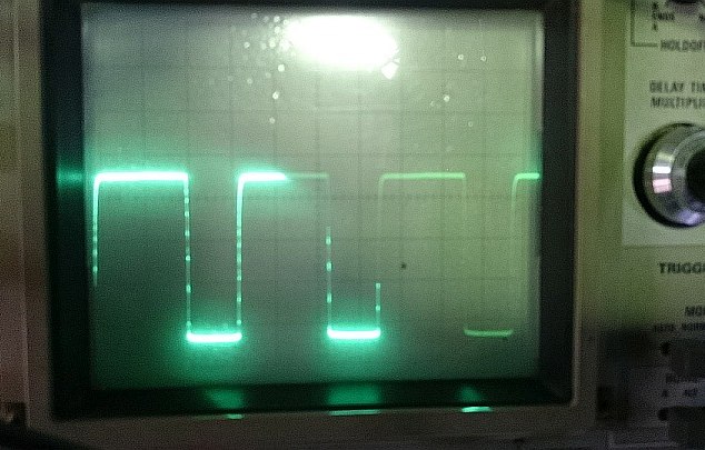
Regarding the home made signal generator, originally
it was a AC adapter of a 6VDC. I added 2 rectifying
diodes inside to get the half-wave rectified waveform
and the full-wave rectified waveform. Using a Schmitt
it was a AC adapter of a 6VDC. I added 2 rectifying
diodes inside to get the half-wave rectified waveform
and the full-wave rectified waveform. Using a Schmitt
trigger circuit, those are converted to square waves of
60Hzand 120Hz. A 4cycles of 4 cylinders engine's
60Hzand 120Hz. A 4cycles of 4 cylinders engine's
revolution 1800rpm means 30rps and the engine ignites
2 times at each revolution. This means that there are
60 ignitions in 1 second. This is the reason why a power
company's 60Hz energy can drive the tachometer
1800rpm and the twice frequency 120Hz, 3600rpm.
This simple method is enough for us to check the
tachometer without buying an expensive signal
generator. This certainly is a poor man's method
but quite effective to check a tachometer as well
as a speedometer since 60Hz drives the speedometer
85km/H and 120Hz, 170km/H.