Mowing machine out of use
p { margin-bottom: 0.25cm; line-height: 120%; }a:link { } p { margin-bottom: 0.25cm; line-height: 120%; }a:link { }
while I was mowing at my vegetable field the other day.

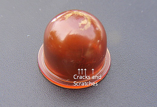
I tried to restart it but there was no luck at all. As I saw
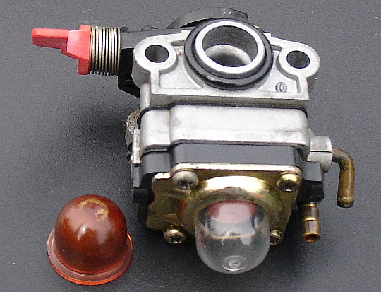
the engine carefully, I found the priming pump cracked
a bit. It was absorbing the air and the gasoline was not
sent to the carburettor. The crack was getting bigger
and bigger as I pushed the bottom side and the gasoline
was leaking out
Without the gas, the mowing machine has no idea to work.
All I needed to do was to replace the pump. But local
shops didn't have the pump at all.
Did I have to buy a new mowing machine?
No kidding! My wife said. She also added,”You always
fix anything except human beings. Why don't you try
to find it on the Net”.
I searched the Net and I found this below.
http://item.rakuten.co.jp/proplace/pp-1/
This costs 378 yen + shipping cost.
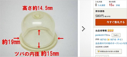
As I searched more and I found this below at the Yahoo
Auction. This is costing only 580 yen for 2 pieces including
the shipping cost. This looked nicer and I decided to
choose this and I ordered 2 pieces.
2 days later, the parts arrived and I quickly installed one
and fixed the mowing machine.
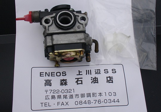
Now it is back to life and working fine. I can resume the
mowing job now.
The seller seems to be running a gas station or something.
I found this below at the Yahoo Auction but the link below
may not effective every day.
http://page9.auctions.yahoo.co.jp/jp/auction/k197870034
May be you can find the part searching the name of
Primary pump WPV12-B.
p { margin-bottom: 0.25cm; line-height: 120%; }a:link { }
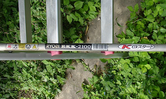
My mowing machine "Ryobi EKK-2100" stopped workingwhile I was mowing at my vegetable field the other day.
I tried to restart it but there was no luck at all. As I saw
the engine carefully, I found the priming pump cracked
a bit. It was absorbing the air and the gasoline was not
sent to the carburettor. The crack was getting bigger
and bigger as I pushed the bottom side and the gasoline
was leaking out
Without the gas, the mowing machine has no idea to work.
All I needed to do was to replace the pump. But local
shops didn't have the pump at all.
Did I have to buy a new mowing machine?
No kidding! My wife said. She also added,”You always
fix anything except human beings. Why don't you try
to find it on the Net”.
I searched the Net and I found this below.
http://item.rakuten.co.jp/proplace/pp-1/
This costs 378 yen + shipping cost.
As I searched more and I found this below at the Yahoo
Auction. This is costing only 580 yen for 2 pieces including
the shipping cost. This looked nicer and I decided to
choose this and I ordered 2 pieces.
2 days later, the parts arrived and I quickly installed one
and fixed the mowing machine.
Now it is back to life and working fine. I can resume the
mowing job now.
The seller seems to be running a gas station or something.
I found this below at the Yahoo Auction but the link below
may not effective every day.
http://page9.auctions.yahoo.co.jp/jp/auction/k197870034
May be you can find the part searching the name of
Primary pump WPV12-B.
Fixing Mitsubishi RDT223WM-S
A young lady mumbled ,
“Should I give up to use this computer display monitor”?
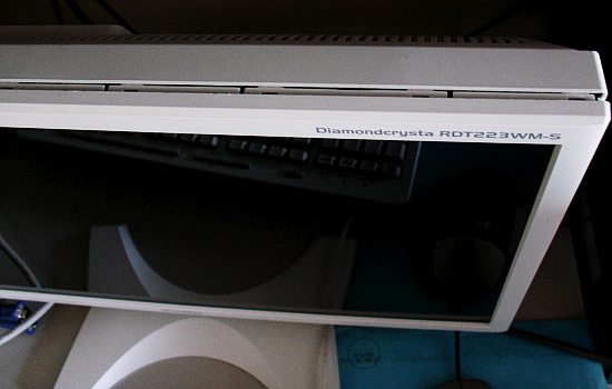
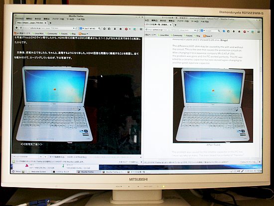
A few days ago her monitor Mitsubishi RDT223WM-S was stopped
working turning the screen all white as is shown below.
She was informed about me from her friend whose laptop was
fixed by me. The monitor is about 5 years old but has an HDMI input
and would be still useful if fixed.

As soon as I saw it, I quickly understood that all the LCD pixels were
completely open due to the no bias voltage to the thin film
transistors (TFT). This simply means that the DC supply to TFTs is
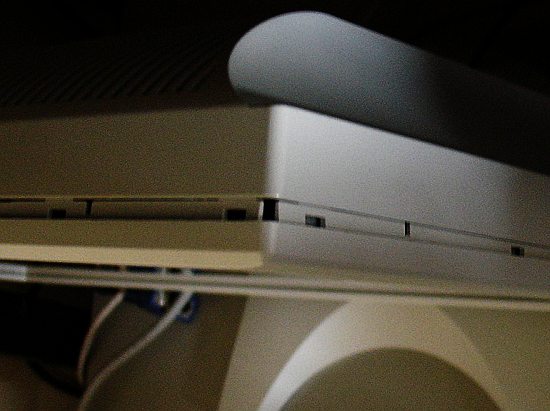
stopped. I wanted to confirm this quickly but it took me nearly an
hour to remove the rear cover. There were too many clips and it
wasn't easy to see inside.
As I checked the DC line there, a fuse to a DC-DC converter was open
as is shown below. This only needed a minute to check.
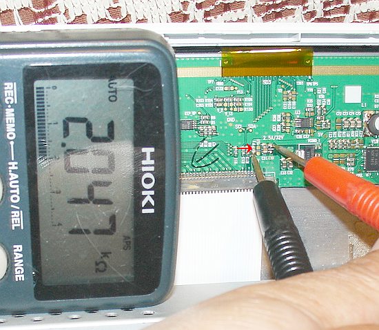
It showed 2.047KΩ although it should be 0.1Ω or less. It was obvious
that there went too much current or the fuse itself may had a problem.
As I checked the current, it showed sometimes 0.4A or 0.7A
depending on signals such as the checker flag, moving square dot
texture and pencil pattern, but never exceeded 1A by my multimeter.
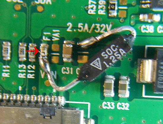
The fuse is so small that I could not identify the part but the silk
print said 2.5A/32V. I dare tried to use a 1.25A fuse temporarily
as is shown below aiming to check it would open or not. Mounting
this stopped all white screen and the OSD appeared.

I also tried tapping the board as well as the whole LCD panel.
The monitor has kept working while tapping with a 1.25A fuse.
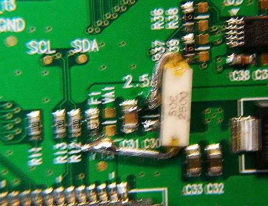
After confirming these, I decided to changed the fuse. The new
fuse is a 2.5A/35V which has the close rating printing on the board.
It would be best to use an exact fuse originally mounted if the circuit
was properly designed but due to the reason of no quick availability,
I dare used the one shown below only because I happened to have
it in my parts box. The photo is blurred but I think you can recognize
the rating.
Come to think of it, the original fuse has failed but the circuit was
OK and the actual measured current was less than 1/3 of the rating.
I am assuming that the original fuse may have some long reliability
problems or the circuit designer's part selection was not good enough.
“Should I give up to use this computer display monitor”?
A few days ago her monitor Mitsubishi RDT223WM-S was stopped
working turning the screen all white as is shown below.
She was informed about me from her friend whose laptop was
fixed by me. The monitor is about 5 years old but has an HDMI input
and would be still useful if fixed.
All white screen
As soon as I saw it, I quickly understood that all the LCD pixels were
completely open due to the no bias voltage to the thin film
transistors (TFT). This simply means that the DC supply to TFTs is
stopped. I wanted to confirm this quickly but it took me nearly an
hour to remove the rear cover. There were too many clips and it
wasn't easy to see inside.
Hard to open
I managed to remove the rear cover and saw inside of the panel driver. As I checked the DC line there, a fuse to a DC-DC converter was open
as is shown below. This only needed a minute to check.
Open fuse
It showed 2.047KΩ although it should be 0.1Ω or less. It was obvious
that there went too much current or the fuse itself may had a problem.
As I checked the current, it showed sometimes 0.4A or 0.7A
depending on signals such as the checker flag, moving square dot
texture and pencil pattern, but never exceeded 1A by my multimeter.
The fuse is so small that I could not identify the part but the silk
print said 2.5A/32V. I dare tried to use a 1.25A fuse temporarily
as is shown below aiming to check it would open or not. Mounting
this stopped all white screen and the OSD appeared.
Checking with a 1.25A fuse
Appeared OSD
I also tried tapping the board as well as the whole LCD panel.
The monitor has kept working while tapping with a 1.25A fuse.
After confirming these, I decided to changed the fuse. The new
fuse is a 2.5A/35V which has the close rating printing on the board.
It would be best to use an exact fuse originally mounted if the circuit
was properly designed but due to the reason of no quick availability,
I dare used the one shown below only because I happened to have
it in my parts box. The photo is blurred but I think you can recognize
the rating.
Come to think of it, the original fuse has failed but the circuit was
OK and the actual measured current was less than 1/3 of the rating.
I am assuming that the original fuse may have some long reliability
problems or the circuit designer's part selection was not good enough.
Alternate fuse
 Actual use after alternate fuse was soldered
So the problem was just an open fuse as I assumed. There are
millions of TFTs and depending on the drive signals, there goes a
big current and the designer should pay enough attentions
on selecting the fuse.
It has been working well for 24 hours after the new fuse was installed.
I will be returning this monitor to the lady soon.
millions of TFTs and depending on the drive signals, there goes a
big current and the designer should pay enough attentions
on selecting the fuse.
It has been working well for 24 hours after the new fuse was installed.
I will be returning this monitor to the lady soon.
NEC PC killed by a ceramic capacitor
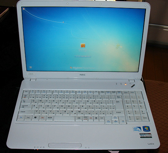
I was requested to fix by a young lady who has been in use of a laptop
NEC PC-LS150BS6W which recently has failed. It is about 3 years old.
It's too early to fail.

As I pushed the power button, all indicators just turned on for a
second then turned off quickly and nothing more happened.
But when the power button was not pushed, charging indicator
kept turning on and the battery was charged properly.
According to her, it was quoted roughly minimum 50,000 Yen to
repair at one of the NEC repair stations. They say the main board
has to be replaced.
As I checked the AC current of the primary side, there went an
inrush current peaking about 1A at when the button was pushed
down and then went down to less than 0.03A.
Judging from the symptom, the charging circuit is OK but an
over current protection circuit in the main board is triggered.
Once it is triggered, there remains the failure status for several
seconds and the power button does not respond during that time
period.
After removing the keyboard, upper side and bottom side covers,
I tried to check the voltage of each line. The CPU power 1.1V
and the memory power 2.5V went up but the logical 5.0V power
didn't go up. It just barely went up to 0.1V or less which was way
too low to work.
I quickly thought there must be a short circuit somewhere.
As I checked the resistance between the 5V line and the ground,
it was around 0.36 ohm at the DC-DC converter block and at
other blocks, the ohm meter said 0.34 ohm or less. The value
0.3 ohm order was too small and there went a big current. That was
the reason why the over current protection circuit was worked.
Next step was to find out the location where the short circuit was
caused. They say that NEC's PCs are infamous for the problem
which is the short circuited ceramic capacitor. Actually, as I
searched the Net, I found many those problems next to next as
are linked below.
http://stretch.main.jp/pc/?cat=28
http://www.pc2.jp/pc/sindan/chipcondensa.htm
http://nahitafu.cocolog-nifty.com/nahitafu/2006/03/pc_c9da_1.html
http://www.tecn-pc.com/index.php?QBlog-20130424-1
http://pcassist.exblog.jp/i5
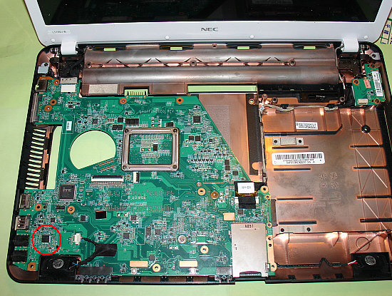
I found the resistance between the 5V line and the ground was the
lowest at the HDMI circuit area. It is indicated by a red circle at the
lower left corner of the 2nd photo.
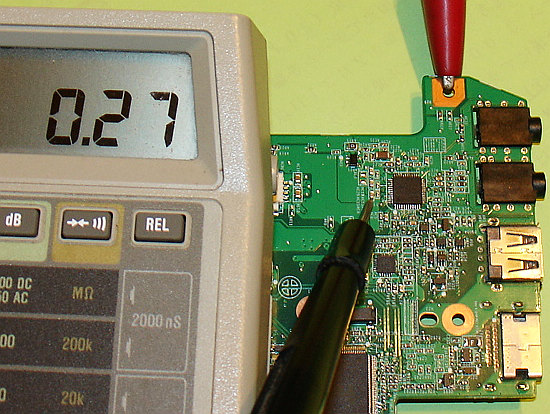
This simply meant that the shorted capacitor must be at the HDMI
circuit area. The capacitor above showed 0.27 ohm but others
0.28 or 0.29 ohm even at the HDMI circuit.
I removed the one which showed 0.27 ohm when mounted and
measured it alone and it showed 0.28 ohm. Bingo!
The difference 0.01 ohm may be caused by the with and without
the circuit. This is the one that causes the protection circuit on.
After changing it to a Japanese company M's 0.47uF 25V,
the problem was gone and the PC worked perfectly. The PC was
killed by a ceramic capacitor but was revived again changing to
another good Japanese capacitor.
The problem was caused by the ceramic capacitor in this PC too.
I must say why so many. The main board has a stamp of “Hanstar”.
I assume that NEC is asking that company to make it but they are
not selecting parts nor controlling the quality well enough.
As long as they sell products putting their name on those, they
should be more careful for the quality issues. The capacitors
problem has been going on for almost a decade and still NEC is
not dealing with it well . I feel sorry for those who bought an NEC
PC which failed.
p { margin-bottom: 0.25cm; line-height: 120%; }a:link { }
NEC PC-LS150BS6W which recently has failed. It is about 3 years old.
It's too early to fail.
NEC PC-LS150BS6W
As I pushed the power button, all indicators just turned on for a
second then turned off quickly and nothing more happened.
But when the power button was not pushed, charging indicator
kept turning on and the battery was charged properly.
According to her, it was quoted roughly minimum 50,000 Yen to
repair at one of the NEC repair stations. They say the main board
has to be replaced.
As I checked the AC current of the primary side, there went an
inrush current peaking about 1A at when the button was pushed
down and then went down to less than 0.03A.
Judging from the symptom, the charging circuit is OK but an
over current protection circuit in the main board is triggered.
Once it is triggered, there remains the failure status for several
seconds and the power button does not respond during that time
period.
Keyboard, upper side and bottom side covers all removed
After removing the keyboard, upper side and bottom side covers,
I tried to check the voltage of each line. The CPU power 1.1V
and the memory power 2.5V went up but the logical 5.0V power
didn't go up. It just barely went up to 0.1V or less which was way
too low to work.
I quickly thought there must be a short circuit somewhere.
As I checked the resistance between the 5V line and the ground,
it was around 0.36 ohm at the DC-DC converter block and at
other blocks, the ohm meter said 0.34 ohm or less. The value
0.3 ohm order was too small and there went a big current. That was
the reason why the over current protection circuit was worked.
Next step was to find out the location where the short circuit was
caused. They say that NEC's PCs are infamous for the problem
which is the short circuited ceramic capacitor. Actually, as I
searched the Net, I found many those problems next to next as
are linked below.
http://stretch.main.jp/pc/?cat=28
http://www.pc2.jp/pc/sindan/chipcondensa.htm
http://nahitafu.cocolog-nifty.com/nahitafu/2006/03/pc_c9da_1.html
http://www.tecn-pc.com/index.php?QBlog-20130424-1
http://pcassist.exblog.jp/i5
I found the resistance between the 5V line and the ground was the
lowest at the HDMI circuit area. It is indicated by a red circle at the
lower left corner of the 2nd photo.
It showed only 0.27 ohm
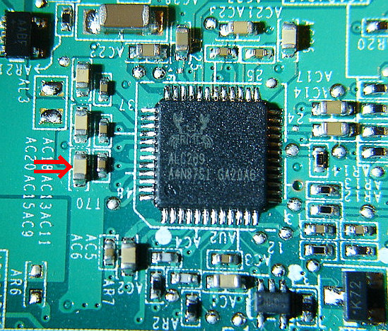 The suspect
At other circuits, the resistance was always higher than 0.30 ohm.This simply meant that the shorted capacitor must be at the HDMI
circuit area. The capacitor above showed 0.27 ohm but others
0.28 or 0.29 ohm even at the HDMI circuit.
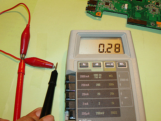
Measuring only the suspect capacitor
I removed the one which showed 0.27 ohm when mounted and
measured it alone and it showed 0.28 ohm. Bingo!
The difference 0.01 ohm may be caused by the with and without
the circuit. This is the one that causes the protection circuit on.
After changing it to a Japanese company M's 0.47uF 25V,
the problem was gone and the PC worked perfectly. The PC was
killed by a ceramic capacitor but was revived again changing to
another good Japanese capacitor.
After fixed
The problem was caused by the ceramic capacitor in this PC too.
I must say why so many. The main board has a stamp of “Hanstar”.
I assume that NEC is asking that company to make it but they are
not selecting parts nor controlling the quality well enough.
As long as they sell products putting their name on those, they
should be more careful for the quality issues. The capacitors
problem has been going on for almost a decade and still NEC is
not dealing with it well . I feel sorry for those who bought an NEC
PC which failed.
p { margin-bottom: 0.25cm; line-height: 120%; }a:link { }
Cracked solder point forced the driver to upset
I was requested to fix intermittent problems no gear shift, no tachometer,
no speedometer by an owner of a local car repair shop.
I know this often happens among some domestic cars.
no speedometer by an owner of a local car repair shop.
I know this often happens among some domestic cars.
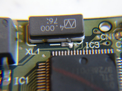
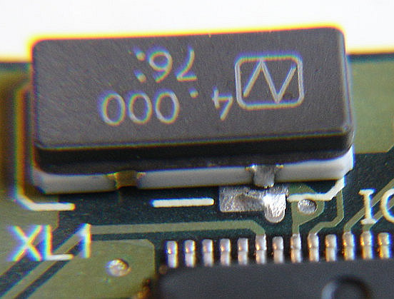
Closer look
The owner must have upset unable to read the speedometer. The AT
didn't shift properly. Without the crystal, the processor had no idea
to work.
didn't shift properly. Without the crystal, the processor had no idea
to work.
This type of problem was often caused by the designer who didn't
know the difference of the expansion rate. They should have known
that how the glass-epoxi and the ceramic had different rates.
Engineers who work for the automobile indutries have to study a lot.
know the difference of the expansion rate. They should have known
that how the glass-epoxi and the ceramic had different rates.
Engineers who work for the automobile indutries have to study a lot.
The replacing job continued
It has been 3 months since I wrote my blog last time. I have been busy as
a community leader but I have some free time now and I just will update it.
#1 upper crank bearing
My trial to insert the #1 upper crank bearing was succeeded like this below.
As you see, there's a big soldering iron attached to the cylinder block.
The block was heated up by a 150W soldering iron.
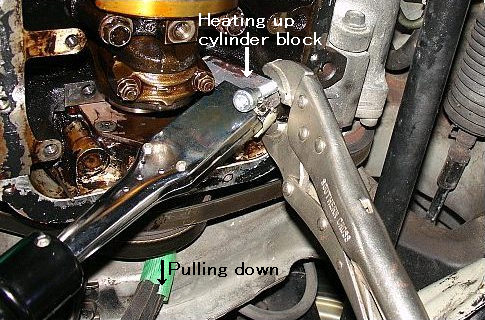
Heating up the block using a big soldering iron
The idea was given by a man who runs a Porsche shop “Garage Neunmeister”.
http://www.garage-neunmeister.com/blog/02/index.html
He is a man who is extremely skilled well. I have never met a mechanic like him
He is a man who is extremely skilled well. I have never met a mechanic like him
in mylife time so far. His advise is always effective to me. I'm not a mechanic
but if I were a mechanic, I'd be wanted to be like him. He suggested me to
warm up the cylinder block up to 100 degrees C. He mentioned, “Since it's
made of the aluminum alloy, the heat conduction is good as well as it expands
more than the iron when heated and it makes the gap between the crank
shaft and the block bigger”. He also calculated precisely and showed me the
data that was almost indicating the high possibility to insert.
The idea was to use a fire frame or something like that but I didn't have any
of those tools. I thought a soldering iron with a flat chip with a couple of
hundred watts would be effective. I actually have a 150W and 300W one.
I tried to use a 150W one first as a trial attaching a pet bottle to the block
to know the temperature since it began to melt at 100 degrees C.
In 15 minutes, the engine oil began to drop like pit a pat. It simply meant the
block was effectively warming up. In an hour the pet bottle attached to the
other side of the block became softer. Finally it began to melt in another 10
minutes. During this, the engine oil was dropping like a rain and was touching
the soldering iron causing a smoke next to next.
I used a thick glove for fear of my fingers to be burnt and tried to insert the
bearing. It was mostly successful. I could insert it up to almost 70% just using
my fingers. Then I used a bamboo stick and a plastic hammer to push it in more.
The bearing was completely inserted and I finally succeeded to install it.
The gap measured by a plastic gauge showed like this below and it was within
the specification.
The clearance #1 upper crank bearing
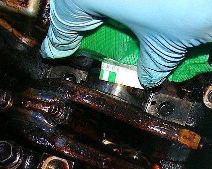
#5 lower crank bearing
It was the last bearing I wanted to replace. Judging from the conditions of
other lower crank bearings, #5 lower must be not good. But it was not easy
to remove easily but I finally succeeded to remove the cap and replaced it.
My idea was to make and use a home made jig like this below.
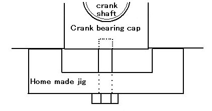
Cap removing jig
The cap has a screw hole at the center. Initially I inserted a bolt there and
pulled it by my hand but nothing has happened. Using a home made jig above
and tried to pull it down. This was quite effective. As I turn the bolt CW, the
cap was coming down little by little and finally it was completely removed.
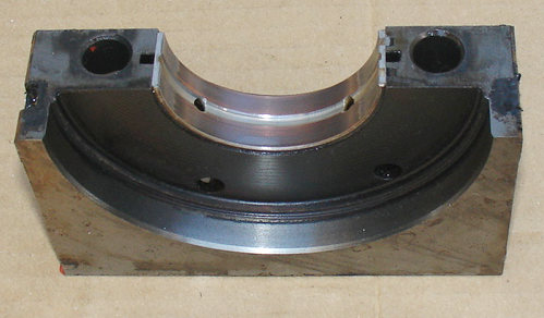
#5 cap and crank bearing

As you see the surface of the bearing, the copper layer is almost exposed.
After the replacing the bearing and two seals located at the side of the cap,
I reinstalled the cap putting some FIPG to those seals. I also used it to the
rear main seal located between the crank shaft and the transmission.
After the job, I reinstalled the oil pan and the exhaust pipe line. Then I filled
the engine oil and I started the engine. The hitting noise at the revving up
was no more there. The engine became quieter and sounded nicely.
Now all 8 rod bearings and 6 crank bearings ( all of lower and 1 upper) were
replaced. There remain 4 upper crank bearings but I'm going to let them be
because they are considered not too bad judging from clearances measured
by the plastic gauge. Also they are not easy to replace.
Full of sludge (4)
I have been busy these days and I haven't been able to do any. But Now
I can write some.
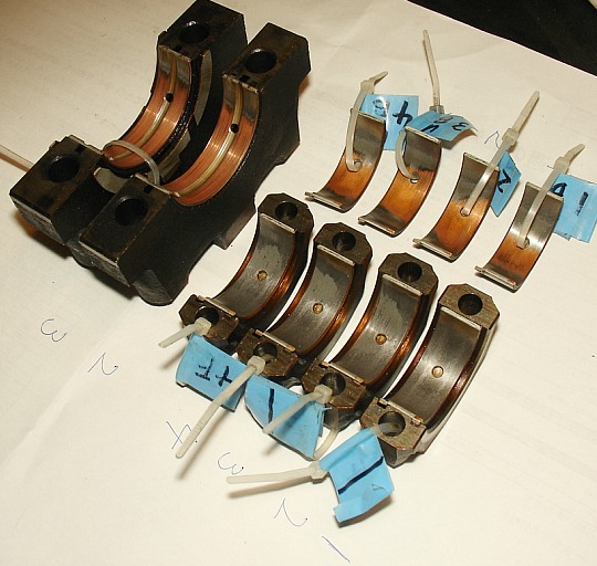
I only have showed you only 2 out of 4 lower crank bearings last time but
I found the photo which included the other 2 of lower crank bearings below
with all the rod bearings.
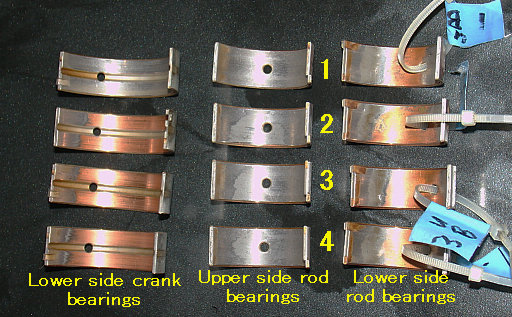
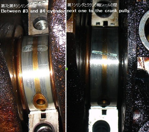
All the bearings removed
As you see #1 lower crank bearing, it is not fully colored copper-red yet
although other 3 are completely so. The #1 is closest to the crank pulley
and the belts are pulling the shaft upward. The force to the upper direction
must have reduced the damage of the #1 lower crank bearing. In other
words, the upper side must have been stressed.
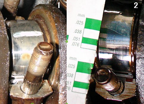
Last time when I checked the clearance here using a plastic gauge, it was
bigger than 0.076 mm. It was so big that the gauge was out of order to
measure the clearance precisely. Later on I understood why so removing
and seeing the #1 upper crank bearing below. You can see how it was
stressed and worn showing the copper base more than other 3 lower
bearings.
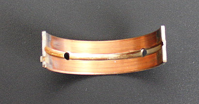
Removed #1 upper crank bearing
Without removing the crank shaft, usually upper side of crank bearings
from the lower side of the engine without removing it. An old skilled shop
owner and a shop owner who runs a Porsche repair shop gave me very
good ideas. To remove the #1 upper side crank bearing, all I needed to
do was just pushed the bearing out some using a small minus driver and
then rotated the crank shaft hooking the end of the bearing by a small
copper piece inserted to the oil hole. The copper piece is softer than the
iron and without scratching the crank shaft and others, the upper side
crank bearing was pushed out completely. Come to think of it, it was
much thinner than the original (about 160um thinner) and it was an easy
job to remove.
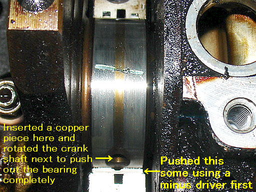
How to remove the upper crank bearing
But to insert a new one was not easy. It was15um thicker than the original
but the old one was worn out and the difference of the thickness was
175um. I tried to insert just pulling the crank shaft downward but I only
could insert only 25%of it. Look at the photo below.
It was scratched, nibbled and bent. The insertion was completely failed.
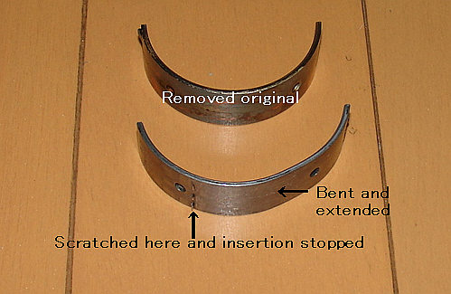
Insertion failed
I will show you how I suceeded at my next post.
Full of sludge (3)
As the 3rd item, I wanted to replace crank bearings and rod bearings as many
as possible. Below are removed bearings. You can see upper side of rod bearings
are worn out and the copper layers are exposed. Lower side rod bearings are also
worn but compared with upper sides they are still better.
I only can show you two crank bearings of lower side. I took two others but I lost
the photo. The one close to the crank pulley did not show any color of the copper.
It may be because of belts pulling the crankshaft up. I imagine the upper side
must be stressed by belts and worn out. But I have no idea to see without
removing it.
Removed bearings

only fix cars just as my hobby and I don’t have equipments such as engine
hanger nor a car lifter. All I can do is to access the crankshaft just removing
the oil pan.
With my limited conditions I was able to replace all 8 rod bearings and 4 crank
bearings out of 10. Those were the replacement job which I could do most under
the car.
I used 30um thicker crank bearings. But I used the regular rod bearings for all 8.
This idea was given by a talented mechanic manager who used to work for Subaru.
As I checked the clearances, rod bearings are all within the spec but the #1 crank
bearing was not OK. The photo below shows how the situation was.
The clearance #1 and #2 rod bearing
#3 and #4
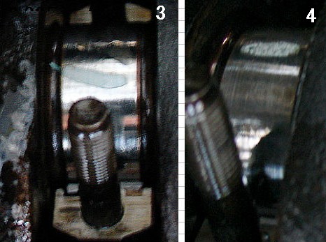
The clearance of # crank bearings.
The photo above right side shows narrower than 0.076mm.
This is not sufficient. Actually, the hitting sound becomes very small but I still can
hear some. I have to do something more but how can I replace those remaining
crank bearings.
A shop owner whom I respect suggetsed me tp replace upperside of crank
bearings teacing me to how to do that without dropping the engine. I am now in
a mood to do so within this autumn.