Another NEC PC killed by a ceramic capacitor
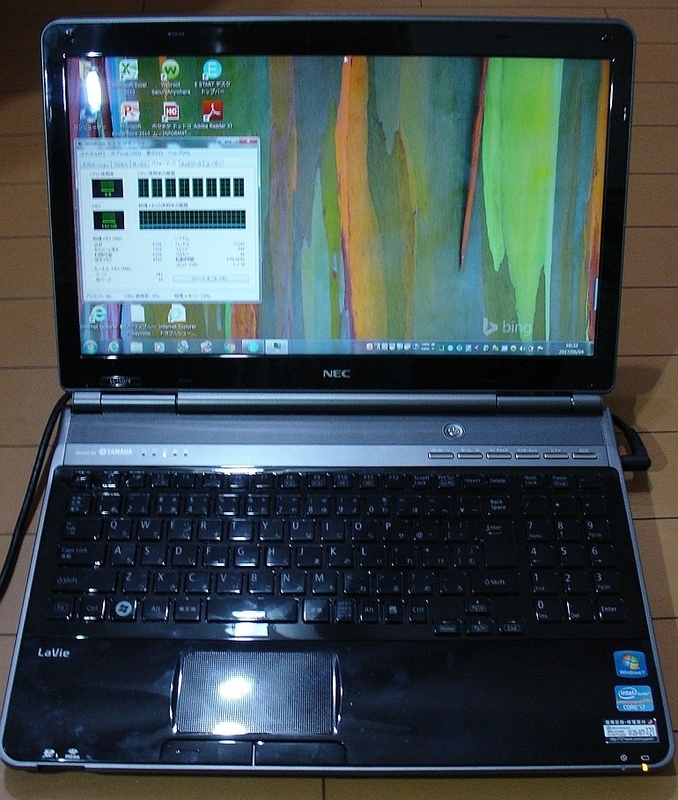
This time, I was requested to fix a NEC PC-LL750F26B. It has a
CPU Core i7-2670QM and the memory 8GB. It's not very new
but it's too early to discard. As you see the photo below, it says
Core i7.
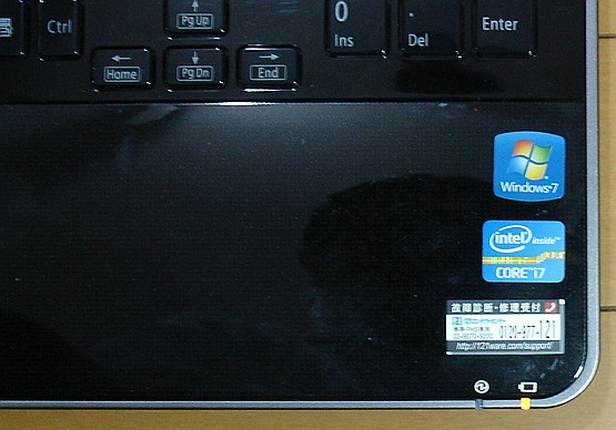 The label says, "CORE i7".
I have once experienced a short circuited problem of a ceramic
capacitor used for a NEC laptop at here.
https://blogs.yahoo.co.jp/mae_yas/11468574.html
As I have written above, there were many similar problems among
NEC PCs in the market. When one of ceramic capacitors used
for the bypass purpose is short circuited internally, it is not easy
to find out which one is failed since there are many other ceramic
capacitors in parallel with it.
The last time when I fixed the lap top NEC PC-LS150BS6W, I only
needed to use a multimeter which can read down to 0.01Ω to
find out the exact short circuited one since it showed the
resistance 0.01Ω smaller than others and rather easy to distinguish.
This time the symptom was completely no power. Nothing has
happened when the power button was pushed on. No LED nor no
screen lit as if the AC adapter / battery was dead. As I checked
the inside using a multimeter, I found the DC line for the primary
side of the CPU power block and others showed only 0.3 Ω or so.
The photo below shows the resistance at the power supply line.
It is close to the connector where the external AC adapter is
connected. It showed 0.30Ω to 0.33 Ω depending on the
pressure to apply to the capacitor's terminals. When the
photo below was taken, I had to hold the camera by my right
hand and my left hand was barely holing the 2 test leads.
I was not able to give terminals enough pressure and the
read out showed 0.33Ω.
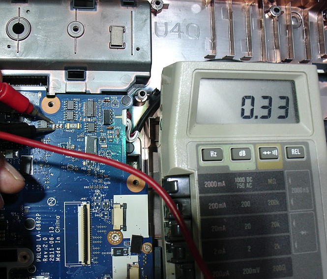 Showed 0.33Ω when leads barely touched
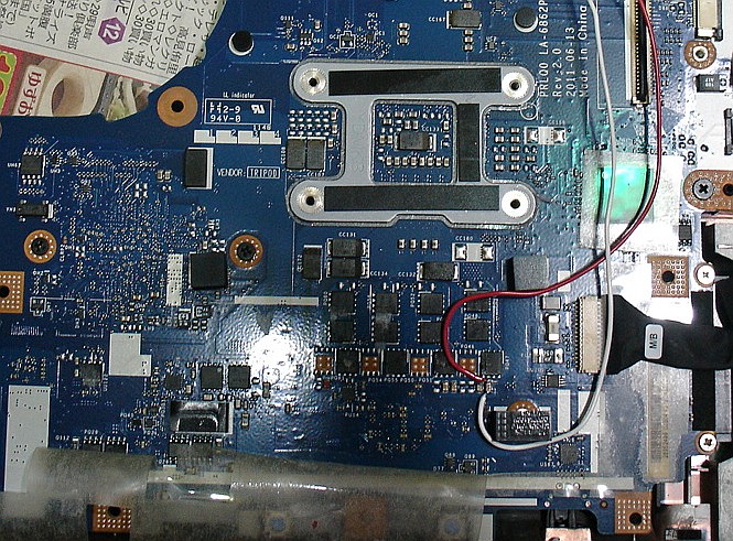
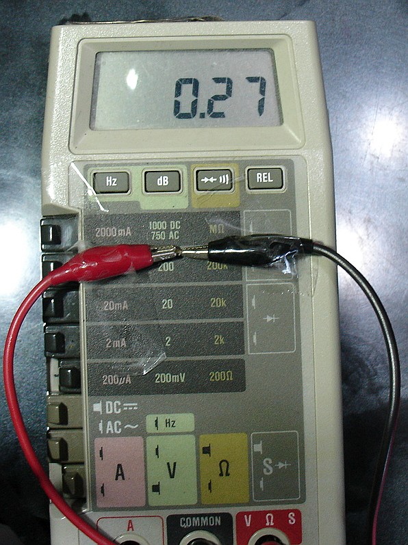
The lowest resistance 0.27Ω was found at the primary side of
CPU's power circuit. There are 4 ceramic capacitors very close
to each other and all of them showed 0.27Ω. The photo below
shows the location where the lowest resistance was confirmed
and I connected wires to supply the current using a low voltage
DC power supply unit. As you see below there are 4 capacitors near
the red and white leads are soldered. All these are in parallel.
Connecting a low voltage power supply unit, I used an infra-red
thermometer which area was warmer than others.
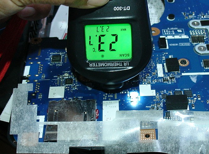
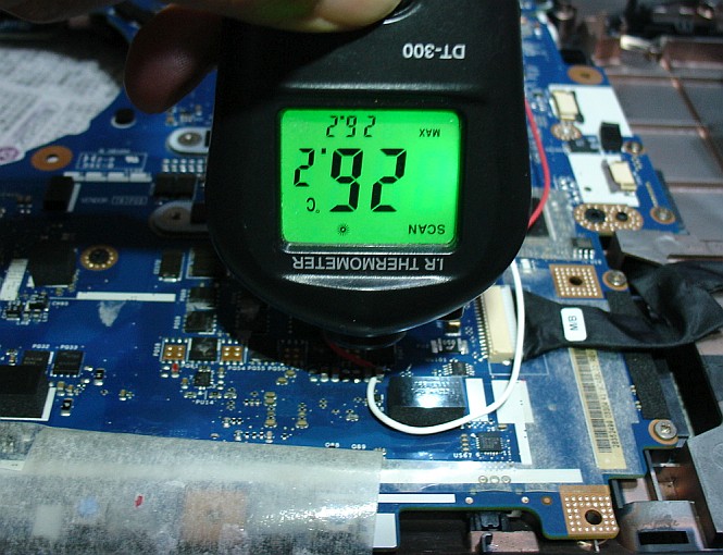
I found that the primary side of the CPU power supply was warmer
than others and this explained why the resistance was lowest there.
I also determined which one out of 4 is failed. The voltage is 0.332V
and this does not go through semiconductors but can go through
resistors. So we can find the semi short-circuited capacitor easily.
There still existed 0.27Ω and this should heat up the capacitor.
Suppose the current is 1A, theoretically the power consumed
by the capacitor is given as follows.
P=I X I X 0.27
For an example, when I is 1A,
P=1A X 1A X 0.27Ω
=0.27W.
The actual low voltage DC power unit is as below.
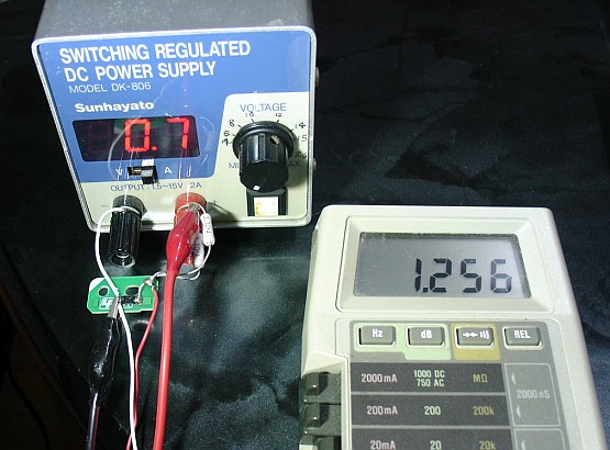
The voltage of the unit is 1.256V when the nob is set minimum
and is still high for semiconductors. So I added 2 resistors in
parallel and a schottkey diode to limit the current and the
voltage. The resistor I used was 1.35Ω(2 X 2.7Ω parallel) and
this limits the current up to 0.93A (1.256V/1.35Ω=0.93A).
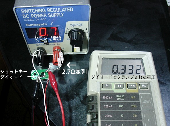
The schottkey diode is EC31QS03L(Io 3A, Vrrm 30V, Vf 0.45V max)
to limit the voltage. In my application, the actual clamped
voltage is around 0.33V or so as you can see in the photo above.
When the output is open, the voltage is limited up to 0.33V and
the maximum current is limited 0.948A theoretically by resistors.
The capacitor had remaining resistance of 0.27Ω and the
maximum current should be limited 1.256V/1.35Ω + 0.27Ω ≒ 0.78A.
Applying the current, I touched the second capacitor from the
right side by my index finger, I felt some extra heat and confirmed
it was the culprit. Replacing it fixed the problem. The removed
capacitor showed the resistance 0.27Ω. I had no idea to know
the original capacitance but judging from the application,
I dare used a 1uF ceramic capacitor manufactured by a Japanese
company Murata which I trust a lot.
Now the PC powers up and works well as it used to be.
I think I need to explain the low voltage power unit a bit more.
In addition to the DC power supply, I used external resistors
1.35Ω(2 X 2.7Ω parallel) to limit the current. The schottkey
diode was EC31QS03L(Io 3A, Vrrm 30V, Max Vf 0.45V) aiming
to limit the voltage. Adding these parts allowed me to supply
the DC to the main board without damaging semiconductors.
This is based on the theory "Fermi level".
CPU Core i7-2670QM and the memory 8GB. It's not very new
but it's too early to discard. As you see the photo below, it says
Core i7.
I have once experienced a short circuited problem of a ceramic
capacitor used for a NEC laptop at here.
https://blogs.yahoo.co.jp/mae_yas/11468574.html
As I have written above, there were many similar problems among
NEC PCs in the market. When one of ceramic capacitors used
for the bypass purpose is short circuited internally, it is not easy
to find out which one is failed since there are many other ceramic
capacitors in parallel with it.
The last time when I fixed the lap top NEC PC-LS150BS6W, I only
needed to use a multimeter which can read down to 0.01Ω to
find out the exact short circuited one since it showed the
resistance 0.01Ω smaller than others and rather easy to distinguish.
This time the symptom was completely no power. Nothing has
happened when the power button was pushed on. No LED nor no
screen lit as if the AC adapter / battery was dead. As I checked
the inside using a multimeter, I found the DC line for the primary
side of the CPU power block and others showed only 0.3 Ω or so.
The photo below shows the resistance at the power supply line.
It is close to the connector where the external AC adapter is
connected. It showed 0.30Ω to 0.33 Ω depending on the
pressure to apply to the capacitor's terminals. When the
photo below was taken, I had to hold the camera by my right
hand and my left hand was barely holing the 2 test leads.
I was not able to give terminals enough pressure and the
read out showed 0.33Ω.
The lowest resistance 0.27Ω was found at the primary side of
CPU's power circuit. There are 4 ceramic capacitors very close
to each other and all of them showed 0.27Ω. The photo below
shows the location where the lowest resistance was confirmed
and I connected wires to supply the current using a low voltage
DC power supply unit. As you see below there are 4 capacitors near
the red and white leads are soldered. All these are in parallel.
Connecting a low voltage power supply unit, I used an infra-red
thermometer which area was warmer than others.
I found that the primary side of the CPU power supply was warmer
than others and this explained why the resistance was lowest there.
I also determined which one out of 4 is failed. The voltage is 0.332V
and this does not go through semiconductors but can go through
resistors. So we can find the semi short-circuited capacitor easily.
There still existed 0.27Ω and this should heat up the capacitor.
Suppose the current is 1A, theoretically the power consumed
by the capacitor is given as follows.
P=I X I X 0.27
For an example, when I is 1A,
P=1A X 1A X 0.27Ω
=0.27W.
The actual low voltage DC power unit is as below.
The voltage of the unit is 1.256V when the nob is set minimum
and is still high for semiconductors. So I added 2 resistors in
parallel and a schottkey diode to limit the current and the
voltage. The resistor I used was 1.35Ω(2 X 2.7Ω parallel) and
this limits the current up to 0.93A (1.256V/1.35Ω=0.93A).
The schottkey diode is EC31QS03L(Io 3A, Vrrm 30V, Vf 0.45V max)
to limit the voltage. In my application, the actual clamped
voltage is around 0.33V or so as you can see in the photo above.
When the output is open, the voltage is limited up to 0.33V and
the maximum current is limited 0.948A theoretically by resistors.
The capacitor had remaining resistance of 0.27Ω and the
maximum current should be limited 1.256V/1.35Ω + 0.27Ω ≒ 0.78A.
Applying the current, I touched the second capacitor from the
right side by my index finger, I felt some extra heat and confirmed
it was the culprit. Replacing it fixed the problem. The removed
capacitor showed the resistance 0.27Ω. I had no idea to know
the original capacitance but judging from the application,
I dare used a 1uF ceramic capacitor manufactured by a Japanese
company Murata which I trust a lot.
Now the PC powers up and works well as it used to be.
I think I need to explain the low voltage power unit a bit more.
In addition to the DC power supply, I used external resistors
1.35Ω(2 X 2.7Ω parallel) to limit the current. The schottkey
diode was EC31QS03L(Io 3A, Vrrm 30V, Max Vf 0.45V) aiming
to limit the voltage. Adding these parts allowed me to supply
the DC to the main board without damaging semiconductors.
This is based on the theory "Fermi level".